In our 101 network TAP series, we have explained the functionality of the various different types of network TAPs as well as some key features. Now we’re going to take a closer look at fiber optics with a focus on fiber polarity.
Usually when you connect two fiber optic devices together, the process goes smoothly. However things can go wrong; where the cable somehow changes which port on the duplex LC connector receives the light. So where the user thinks the TAP is defective, it’s really not the case all at.
First, let’s talk about a router and switch connected together. The fiber optic cable between the two is a crossover cable - this connects the light from the TX of one device to the RX of the other.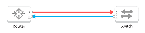
Notice the light ingresses the right side of the SFP connector or LC coupler in both cases (with the tabs oriented up). The crossover cable makes sure of that.
Garland Technology’s fiber optic TAPs follow the same convention on the network ports. We want the light to ingress the right side of the LC couple with the tabs oriented upward.
Light ingresses the network port and travels down an optical device, then is split, exiting the optical splitter out two ports on the other end. One of those goes out the other network port and the other goes out the monitor port.
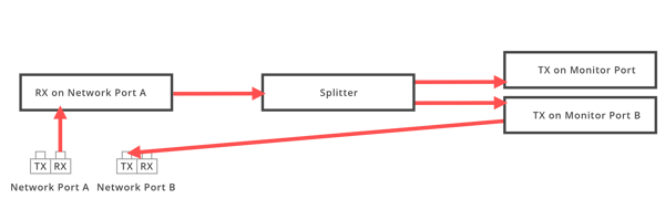
In the figure above, the light ingresses the RX port on port A of the LC connector and enters the splitter. The light traverses the splitter, and since light travels in a straight line, some light will egress the two outputs on the right side. Thus we will achieve what we want, light egresses the TX port on port B, and some light egresses one of the monitor ports.
Likewise, the light would enter the right side of network port B, and would egress the TX port of port A. Some light will also egress the monitor port. (Note: This path isn’t shown, but it is the same as the path from port A to port B and the monitor port. This path uses a second splitter.
Now let’s talk about how something can go wrong. For some reason, the cabling ends up with the wrong polarity, so that when the fibers are plugged into the network ports on the TAP they send the light to the left side of the LC coupler instead of the right side.
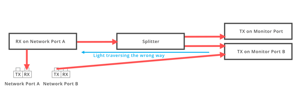
The figure above shows what happens when we reverse the light path. We still have a straight line path from the light ingressing port B going to port A. So the light still makes its way from the device connected via port B to the device connected via port A of the TAP.
But we have a problem. There is no straight line path for the light to egress the monitor port. In the figure above, the light is now entering the side of the splitter which should be the egress. But since the splitter isn’t designed to send that light out, so we get a very weak signal out the monitor ports, if any at all.
The Solution
It’s a fairly simple solution; unplug the LC couplers on the TAPs’ network ports A and B and reverse the polarity, only at the end connected to the TAP. If you were to reverse the polarity at both ends, we’d be back to where we started.
So in a nutshell, if the devices connected to the TAPs’ network ports link, but the monitoring ports don’t, we often have fixed the problem with reversing the polarity on the network ports. Of course, this is assuming that the correct SFPs were used in the devices connected to the network and monitor ports.
Looking to add fiber TAPs to your security deployment, but not sure where to start? Join us for a brief network Design-IT consultation or demo. No obligation - it’s what we love to do!