

As we begin seeing much higher bandwidth speeds for data communications using fiber optical connections and enter into the non-linear world of photonic communications, many things will change from understanding the basic physics of non-linear photonic communications to the increased need for better plant build-outs, an understanding of optical budgets (referencing signal to noise requirements), maintenance, and a much higher requirement for documentation and record keeping.
The most important consideration in deploying a fiber optic network is quality. Quality should always be your No. 1 thought when purchasing optical network components. It’s vital to make sure that you have REAL test measurements for each component and not “average” or “nominally” numbers.
Learning about photonics or optical communications is a true lesson in the non-linear physics of transmission by light, a very interesting and enlightening topic for managers. One should at least know the basics, as that will help them truly understand the complexity in building an optical network and assuring that once built properly it can last many carefree years.
Fiber cannot be thrown around, wrapped and tied in knots like Cat 5/6 copper cables. Each type of fiber has a maximum bend radius which if exceeded will cause distortion and may break the fiber internally. The good thing about fiber is that it is immune to RF radiation from A/C and other electromagnetic sources. Another important item with fiber is that one must take into consideration the correct distances for each cable need. The longer the fiber the larger potential for affecting the signal to noise ratio.
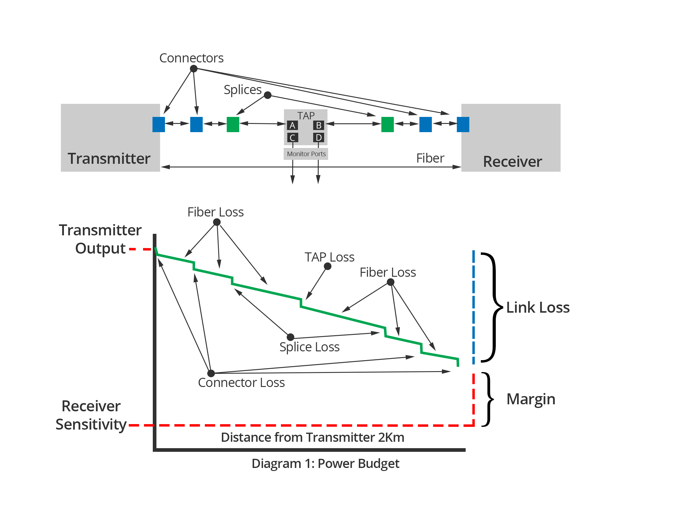
This is the most challenging part of designing an optical network, and one must always consider this as the most important part of a quality and successful data network physical layer. Optical devices are measure in “dBm” for power and optical loss is measure in “dB” with loss always being represented as a negative number. The “m” in dBm refers to the reference power of 1 milliwatt. Thus, a source that has a power level of 0 dBm has a power of 1 milliwatt. And -10 dBm is 0.1 milliwatt and +10 dBm is 10 milliwatts…etc.

| 3 dB | 2 times the reference power (gain) |
| -3 dB | 1/2 the reference power (loss) |
| 10 dB | 10 times the reference power (gain) |
| -10 dB | 1/100 the reference power (loss) |
| 20 dB | 100 times the reference power (gain) |
| -20 dB | 1/100 the reference power (loss) |
| 30 dB | 1000 times the reference power (gain) |
| -30 dB | 1/1000 the reference power (loss) |
The optical budget is the result of considering the power of the transmitters, the attenuation or loss of the connective devices, the fiber quality, the connectors, tension on connectors, dirty connectors, splices, transmission modulation...etc. These measurements should be made by your engineering team and be kept in records for future review. Optical equipment does age so as time goes on and one starts to see physical layer issues these measurements should be revisited.
The standard fiber optic connectors have average "nominally" losses – but can vary with the quality of the connector (the ferrule), the fiber endface design and polish quality.
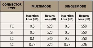
Some of the most common fiber optical connectors available on the marketplace today include:
**SMA, FDDI and Biconic connectors are almost obsolete in new fiber technology deployments.
Once you have all the power in and loss figures, you have the optical budget for that optical path, and now you will know if design and or equipment changes are required to assure a low loss physical transport.
A properly installed fiber optic cable plant needs no scheduled, routine maintenance. Actually, unless your technicians are extremely careful and meticulous, and even that may not be enough, maintenance on a fiber optic network can create more problems than it solved.
Let’s take a look at some of the problems commonly associated with fiber networks and how we can prevent them. First, dirt and dust are the most common reason why there are problems with the connections points in the network. Dirt can scratch the ends of the connectors, causing a higher loss in the mated pairs of connectors.
Dirt, moisture, etc. can get on the ends of the connectors when they are exposed to the air and moisture (moist air also contains other contaminants, such as bacteria and fungus) and cause both high loss and high back reflection.
Connector ends should be assured they are clean when mating initially! To achieve this, cable connectors should be stored with their dust caps in place at all times, and always be stored properly in a dry clean environment. All companies should have a fiber optic maintenance policy in place that state how fiber cables and connectors will be inspected prior to installation.
Question: What are these pictures of?
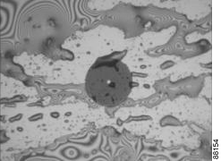
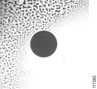
Answer – Connectors with contamination
The final piece to the puzzle. Each device, cable, etc. should have a label and permanent records associated with it.
All this information should also be in a log book or file to be updated if the connectors are opened, equipment changes, power and loss measurements…etc. and a label attached to cable for instant ID and info. The more information you keep will help in network plant changes and troubleshooting issues.
So, fiber optics seem easy and simple but unlike the physical layer for low speed communication the fiber optic plant must be designed for optimal passage of high speed data.
Want to learn more about the different connectivity strategies to choose from for your network? Download our whitepaper, Network Connectivity: Basics and Beyond today.