I’ve previously provided an introduction to Cisco ACI in terms of facilitating a next-generation data center by taking advanced of software defined networking. So if you haven’t read that post, it’s a great place to start.
Abstraction is a key concept in administration, scaling, and deployment automation within Cisco ACI. This is accomplished by defining endpoints and policies that determine how data flows through the ACI fabric.
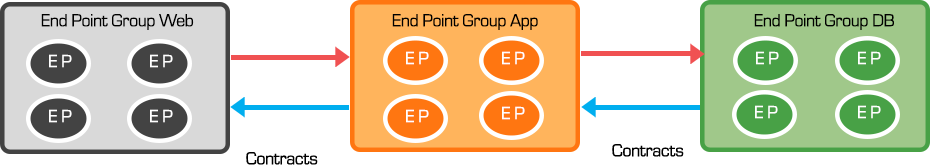
End Point Groups are used to identify and group application endpoints. By default, endpoints within an endpoint group can communicate with each other, but communication between endpoint groups require contracts. These contracts define policy that determine how EPGs communicate with each other. A contract typically refers to one or more filters to define specific protocols & ports allowed between EPGs. This abstraction layer detaches security policy from infrastructure such as specific IP address or VLANs. Utilizing EPGs/Contracts, network policy, L4-7 Security and forwarding are abstracted from underlying hardware and applied consistently for any workload.
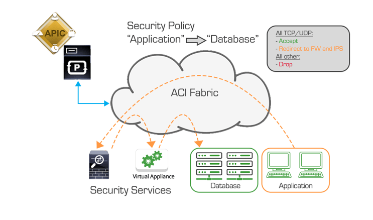
Service Graphs add L4-7 security services to workloads (physical or virtual) independent of location. This enables automation and deployment of advanced protection with NGFW, IPS/IDS, DDoS Services Insertion. With service graphs, traffic can be steered to specific L4-7 devices by the defined policies.
Service Graph technology was designed to automate and accelerate the deployment of L4-L7 services in the network. Using Service Graphs, a security service/device is fully inserted to the Application by sending defined traffic to the Security Service using the contract. Beyond automation and scripting efficiencies, multiple services can by inserted seamlessly with Service Chaining.
There are two management models that allow full flexibility for security administrators to maintain their device infrastructure. Requirements must first be defined to match needs and operation model of the Datacenter and Security Teams. There are multiple options to deploy these services including inserting Service Graphs in Network policy (unmanaged) mode or Service manager mode. This allows for SecOps to maintain management workflows and full access to product features.
One of the key considerations in Cisco ACI device abstraction is placement of traditional ‘edge’ devices like firewalls. In traditional networks, firewall placement was typically at the network border interfacing between DMZ environments and WAN connections. With Cisco ACI, physical placement of the firewall is not important as traffic directed in/out of a device will be determined by EPC and Contract definitions. From a monitoring and device management perspective, this is important as it will affect issues like how these inline devices are administered, how these devices are maintained, and how best to monitor traffic flows in and out of these devices.
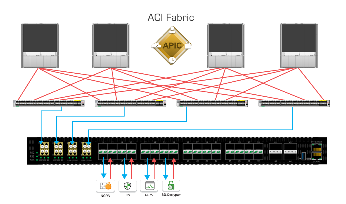
Cisco ACI supports traditional monitoring options including Access SPAN. Access SPAN will mirror traffic locally and allow visibility into traffic to/from the same leaf switch or across multiple leaf switches. Using SPAN aggregation with Garland Technology’s PacketMAX™: Advanced Aggregators or EdgeLens®, SecOps and NetOps teams can extract wider level of visibility across the Cisco ACI fabric from individual leaf switches.
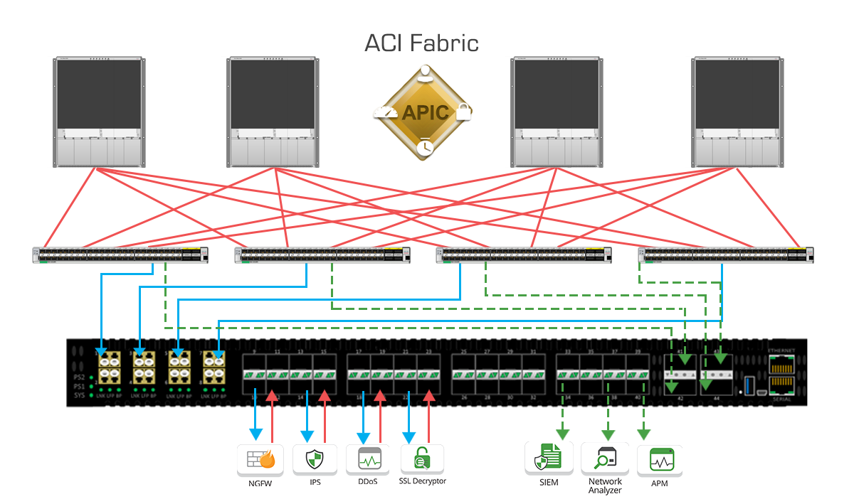
With flexible inline security appliance options and additional visibility options, Garland Technology’s EdgeLens is a perfect complement to help manage and monitor the Cisco ACI network edge. The system facilitates complete lifecycle management of up to four (4) inline service appliances, while replicating or aggregating traffic for use with out-of-band tools. As Cisco ACI enables new flexibility in placement of inline devices, EdgeLens can be used to TAP links between inline tool sand leaf switches. EdgeLens further allows for full bypass functionality with Garland’s fail-safe technology providing enhanced network uptime. EdgeLens can also be used to manage Cisco ACI service insertion by managing appliances like NGFW/NGIPS and SSL decryption devices.
The benefit to deploying EdgeLens is that Network Operators now have ability to guarantee network uptime while deploying or maintaining these devices during scheduled maintenance windows or untimely events like device failures/outages.
A copy of this live, inline traffic can be captured at both ingress and egress, and distributed out to out-of-band tools like a Network Analyzer, SIEM, or Application Monitoring Tool. This ability to mirror inline traffic allows these functions the ability to report and alert network or security events in real-time and in concert with service insertion Cisco ACI policy deployments.
In addition to the integrated TAPs, external TAPs from other locations in the network can feed monitor traffic into the available packet broker ports as ingress links. The EdgeLens can then provide filtering, aggregation, and load balancing for all these different incoming sources of data and distribute to one or many different network/security tools.
In summary, Cisco ACI introduces several software defined innovations in deployment/maintenance simplicity, management, and automation. These deployment innovations are extended to inline deployments like NGFW/IPS through service insertion. EdgeLens enhances these inline and service deployment options by maximizing network uptime while adding visibility and management options. In addition, EdgeLens can be used to aggregate Access SPAN traffic from additional Cisco ACI Leaf switches increasing overall visibility and efficiency of both inline and out of band network/security tools.
Looking to add visibility to your SDN deployment, but not sure where to start? Join us for a brief network Design-IT consultation or demo. No obligation - it’s what we love to do!