Do you know what a Split Ratio is on a fiber network TAP? Well there was a time when I didn't, either. But I know what a seven-ten split is in bowling and I know what it means to “split hairs,” but I didn’t know what a “Split Ratio” was until I started to work on designing and installing a fiber link on our network.
A split ratio is the amount of light that is redirected from the network to the monitor ports on a passive fiber optic network TAP. To determine the correct split ratio, a loss (power) budget should be calculated (more on that later). A 50/50 split ratio would indicate that 50% of the light budget coming into the TAP from the network is passed along to the end device, and 50% of the light budget is diverted to the monitoring device.
To understand how this goes as you change the ratio, for a 70/30 split ratio, 70% of the light budget is passed along to the end device and only 30% of the light budget is passed along to the network monitoring device.
A loss light budget is the amount of attenuation that can be tolerated on the network and monitor links before the end-to-end data is corrupted. To calculate this, one must know the following network link characteristics:
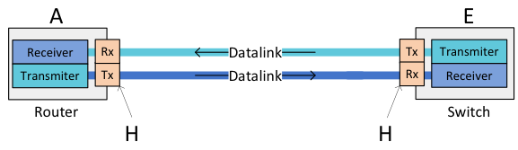 Figure 1: Figure 1:Simple sketch of a data link
In Figure 1, the only loss to be concerned about is the loss along the fiber and the connectors.
In most applications, the 50/50 split ratio will work properly. In the event there are unusual factors at play, there are other split ratios available; 90/10, 80/20, 70/30 and 60/40. Once you figure out your Loss Power Budget using a "Loss Budget Calculator," you should be able to figure out the split ratio that you will require.
The introduction of passive network TAPs into the data link will take a bite out of the light budget.
Fortunately the bite is adjustable. Depending on where the TAP is located in the data link or where the monitoring device is located, the amount of light that is diverted from the data link to be sent to the monitor port will vary.

This is where the split ratio comes into play. By splitting a portion of the total light budget away from the data link, to send to the monitor port, the “Split Ratio” becomes the ratio between network light stream that continues on to the far end device and the light stream that goes to the monitor port.
The loss budget has two uses, first, during the design phase to ensure the cabling will work with the links and second, after installation, by comparing the calculated loss to test results to ensure the cable plant is installed properly.
When comparing Budget Light Loss from TAP vendors, be aware there are not industry standards for measurement. In the network TAP arena, each manufacturer measures and publishes their own data based on their own standards and measurements. Here at Garland Technology we publish ours based on the loss number through our splitters plus what we think the loss number will be through one mated pair (two LC mated terminals).
For more information on our budget light loss measurements, read Loss Though Fiber Optic TAPs, by Jerry Dillard, CTO/Co-founder of Garland Technology.
Looking to add fiber TAPs to your next deployment, but not sure where to start? Join us for a brief network Design-IT consultation or demo. No obligation - it’s what we love to do!