Years back, companies within our critical infrastructure sectors realized that if they wanted to improve their strategic planning and scale their operation, they needed to remove silos between their production and business operations. This meant increasing the connectivity between industrial control systems (ICS), its operational technology (OT), and the business network with its information technology (IT) systems. The primary objective of these digital transformations was to align organizational architecture and centralize data and process flow.
Unfortunately, the convergence of OT and IT systems had unforeseen consequences. It increased cybersecurity vulnerabilities by widening the attack surface and creating visibility challenges. This prompted, in the 1990s, the creation of the Purdue Model. Adopted from the Purdue Enterprise Reference Architecture (PERA) model, the Purdue Model is the framework designed for network infrastructure engineers to segment ICS and business systems properly.
Despite the improvements, ICS and OT networks remain at high risk. With so many sensors, servers, and Internet-of-Things (IoT) devices used in essential verticals like manufacturing, energy production, and transportation, the likelihood of a successful cyber attack is higher than ever. It also leaves the potential for detrimental impacts to the business and the entire industry it serves — putting visibility at the top of mind for OT network engineers.
Before diving into the OT visibility solutions, it's essential to understand the components of the Purdue Model. Intended to provide a framework for network segmentation in ICS architecture, the Purdue Model groups and isolates technology, resources, and systems. It allows businesses to prevent complete operational collapse should one of the segments shut down due to a cyber attack, natural disaster, or other incidents.
The framework uses a six-level system, each of which represents a network or network group:
Companies still face various challenges, even with the Purdue Model supplying a solid foundation for segmenting an ICS network and securing it against OT threats. They want all business and production networks aligned with one another and to aggregate data traffic from all resources and facilities into one system. The issue comes down to designing the blueprint for this level of connectivity that supplies adequate infrastructure visibility.
At first glance, the apparent roadblock is that all resources, tools, and devices, along with their respective connections, will run at different speeds. This prevents businesses from being able to obtain accurate, real-time network data. Another problem is the current monitoring solutions available. Many companies still rely on legacy solutions like switch port with analysis (SPAN) technology for network traffic intelligence.

Unfortunately, SPAN isn't always reliable or secure. They often trigger false alerts and yield lower processing capabilities — quickly becoming overloaded by network bandwidth where it will sporadically drop packets. SPAN also alters frame-interaction timing, which creates inconsistent response times. Finally, SPAN ports are completely open and susceptible to breach. Threat actors can hack SPAN ports, alter data visibility, and prevent users from detecting the breach.
Luckily, there's a great solution to simultaneously maintaining network segmentation between business IT and industrial OT without compromising visibility. One that even works for ICS networks following the Purdue Model.
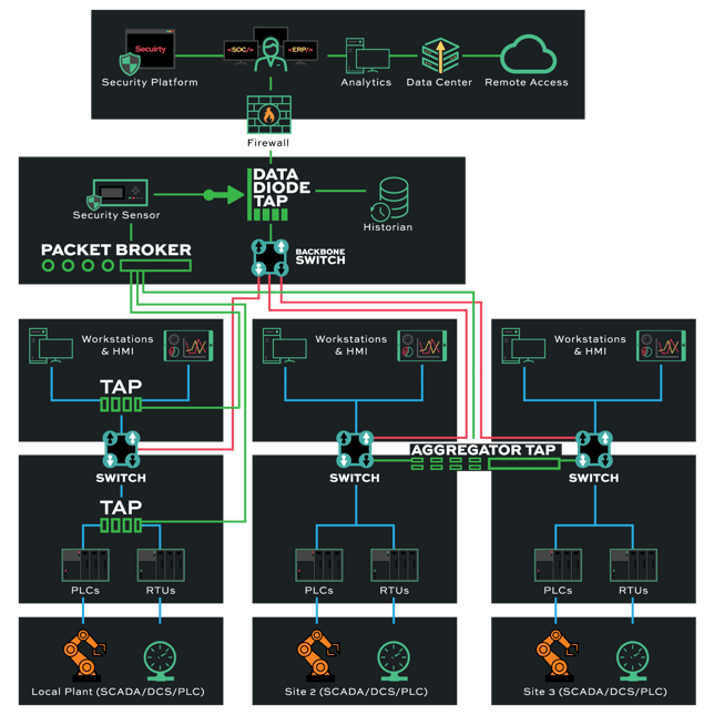
The best visibility solution uses a network test access point (TAP) to facilitate OT network visibility. In this process, network TAP hardware is installed on a network between routers, switches, and network firewalls, an alternative to connecting network routers and switches directly. Once implemented, it collects and copies data packets from separate channels and sends them to a central monitoring device.
Engineers can seamlessly integrate TAPs into ICS and OT networks that follow the Purdue Model. By deploying TAP devices between routers, switches, and firewalls at each segment level (0-5), users can maintain a robust brokering system that routes all streams to the monitoring device. This ensures every bit of data gets observed for security analysis without compromising data integrity or dropping packets due to bandwidth issues.
Using Data Diode TAP devices within an ICS network that follows the Purdue Model is another way to maximize security, particularly for critical infrastructure environments like nuclear plants or transportation systems. Data Diode TAP does not send traffic back into the network. Instead, it's a one-way data flow from each network segment to the central monitoring device.
The uniflow of data and hardware separation offered by Data Diode TAP makes it ideal for placing at higher enterprise levels of the Purdue Model (4-5). Cyber threats that target a business's IT system, for instance, wouldn't be able to trickle down into its OT systems. Network TAPs are a low-cost, scalable solution that's easy to install, provides 24/7 monitoring, and cannot be hacked, as it doesn't have an IP or MAC address.
Looking to incorporate network TAPs into your visibility strategy but not sure where to start? Join us for a brief network design-IT consultation and demo. No obligation - it's what we love to do!