As networks continue to grow and threats become more pervasive, the need to react quickly to changes in the state of your network is higher than ever. One way of making your control over your network more agile is through Software Defined Networking (SDN).
Many networking devices now take advantage of a separated control and data plane architecture. Think of the control plane as a GPS and the data plane as a vehicle: the GPS calculates the best way to get to a destination and makes routing decisions. The GPS then tells the driver of the vehicle what they should do when they don't know the way. If the driver already knows where they are going, they can work autonomously of the GPS.
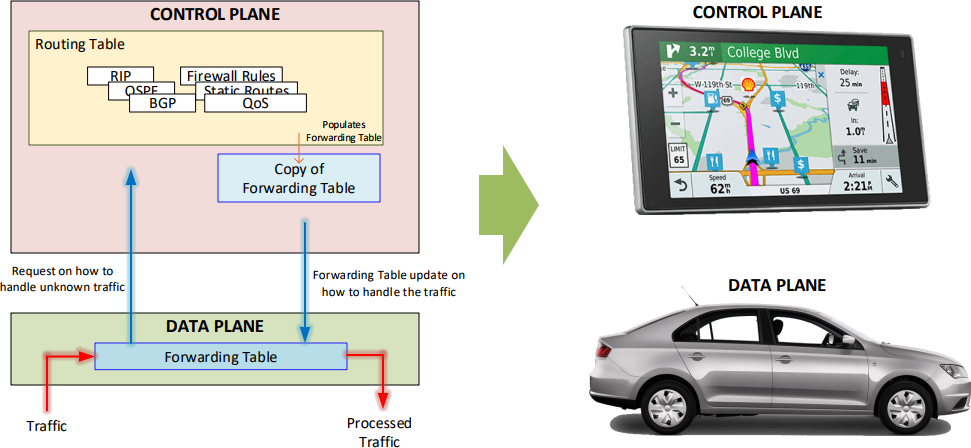
When networking devices follow this set up, it allows the hardware to be purpose built for the task it will be accomplishing. These purpose-built hardware components are called Application Specific Integrated Circuits (ASICS) and are extremely optimized for specific tasks like forwarding traffic, working through complex computations, decrypting traffic or filtering data. SDN takes full advantage of this architecture by focusing on the control plane while allowing the data plane to continue with its tasks.
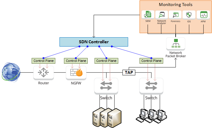
SDN provides the means to configure all the control planes in your network from a centralized location with the use of OpenFlow. Traditionally, network devices were installed inline where each device was physically connected to each other, and needed to be individually configured on how to direct traffic from device to device. With SDN, new or updated configurations can be created for many devices at once, tested, and then pushed out to each device. Using virtualization, SDN can also quickly create and add additional network functions into a network.
The ability to make network-wide configuration changes and even automate these changes makes SDN an incredibly powerful tool, but knowing when these changes need to be made requires complete visibility into the network. Accomplishing this requires multiple monitoring tools, ranging from System Information and Event Management (SIEM) appliances like the Juniper Secure Analytics series to Threat Intelligence security solutions like Centripetal’s RuleGATE.
RuleGATE is a high-speed Threat Intelligence Gateway that will evaluate each packet within the micro-second it takes to pass by the appliance. RuleGATE can also monitor internal traffic to detect and identify command and control feeds from infected hosts. Event logs of each packet can then be sent to a SIEM appliance using a detailed Common Event Format instead of Syslog, reducing the time it takes to establish a root cause analysis of a threat down to seconds.
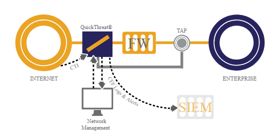
Having the ability to quickly make changes to all areas of the network allows security engineers to rapidly mitigate security breaches and attacks at a network-wide level by blocking interfaces & updating security policies on firewalls. Placing Garland Technology Network TAPs in key points of traffic in the network will ensure the monitoring tools are seeing every bit, byte, and packet.®
Eventually the demands of the network will outgrow the existing infrastructure, requiring upgrades from 10G to 40G and even 100G. Each speed range utilizes different types of connection media: 10G Multimode uses LC SFP+, 40G Multimode utilizes MTP/MPO-12 QSFP+, and 100Gs can use MTP/MPO-12 QSFP28-SR4 or MTP/MPO-24 with an SR10 connection. Making the jump up in speed can lead to difficulties connecting existing monitoring equipment to the new connection media.
The solution? Using a Network Packet Broker.
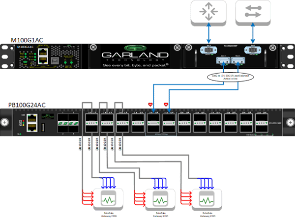
In the diagram above, the customer wants to implement RuleGATE Threat Intelligence Gateways into their 100G connection between the switch and router. The issue in this build is that the RuleGATE appliance only has SFP+ ports which are incompatible with the 100G connection.
In the solution diagram, the 100G connection is being tapped by a Garland Technology 100G Bypass TAP. Connecting to the monitoring ports coming from the Bypass TAP is a 100G PacketMAX Network Packet Broker. This setup allows the data from the 100G link to be copied over to a Network Packet Broker that will be able to transfer the data to a different medium. Additionally, the bypass functionality of theBypass TAP will provide resiliency to this deployment allowing thePacketMAX to be placed inline while preventing it from being a point of failure in the network.
ThePacketMAX has twenty 40G QSFP+ ports and four 40/100G QSFP28 ports. The 100G monitor links from the Bypass TAP will be connected into the QSFP28 ports. To get the required 10G LC connections for the RuleGATE appliance, the QSFP+ ports will use a breakout cable which will provide four 10G links with LC connectors. In total, six QSFP+ ports will need to be utilized. Each QSFP+ port provides 40G of throughput and three sets of 40G will provide enough bandwidth to support the 100G of throughput. Because the 100G network link is bi-directional (router-to-switch and switch-to-router), there will need to be two sets of three QSFP+ ports: one for eastbound and one for westbound traffic.
This is an excellent example of the versatility of Network TAPs: The ability to provide full network visibility, increase the resiliency of the network, facilitate network upgrades, and extend the lifespan of appliances in the network.
Looking to add visibility to your SDN deployment, but not sure where to start? Join us for a brief network Design-IT consultation or demo. No obligation - it’s what we love to do!