

The Network Edge is one of the most important aspects of a network: it facilitates the ingress, egress, security, and optimization of network traffic. Any downtime in the edge will have a direct, negative effect on productivity and will eat into profits. For this month’s Design-IT scenario, I came across an interesting bypass tap solution for the network edge: by using a bypass tap, additional resiliency can be provided to network edge devices. Packet capture can also be offloaded from security devices, allowing the appliance’s resources to be dedicated to what they were intended for.
.png?width=600&name=Bypass%20Tap%20-%20Full%20(1).png)
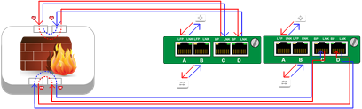
Scenario: The client had redundant WAN connections that they wanted to aggregate into their security appliance and was also looking to implement Forcepoint Data Loss Prevention (DLP) into their network. Their design requirement was to have the DLP appliance receive both ingress and egress traffic from the firewall.
Solution: 2U Chassis populated with four (4) 1G Copper Filter Taps and two (2) 1G Copper Bypass Taps set in bypass mode. The Filter Taps can pass traffic to the bypass taps while also utilizing the chassis’ 1G backplane to aggregate both network links to monitoring tools. There’s a lot going on in the above diagram, so let’s break this down for the sake of clarity:
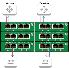
Since we have multiple taps that need to be utilized in this chassis, we need to have traffic flow through each one. To accomplish this, the router is connected to Port A of the Filter Tap in row 1. The eastbound traffic from the router will ingress into Port A and will egress out Port B, ingressing into Port A of the Bypass TAP in row 2. The same thing will happen again: the ingress traffic into Port A will egress out Port B and into Port A of the Filter TAP in row 3. Now, the ingress traffic into Port A will egress out to the network switch and on to device in the local network. This process will follow the same path in reverse with the westbound traffic coming from the switch to the router. Both network links will be set up the same way.
As traffic is sent to the Bypass TAP, it will be redirected to the monitor ports which connect to the network security appliance. Once the appliance processes the traffic, the traffic will be sent to the adjacent monitor ports and flow back out the egress network port.
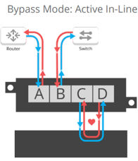
This allows the appliance to act like it is in-line, but physically be out-of-band in the event of a failure. The Bypass TAP will send out small heartbeat packets to the security appliance at a rate of about 20 packets a second. On the return trip back, the TAP strips these packets, ensuring additional bandwidth is not added to the production network. In the event of a device or a link failure, the heartbeats will let the TAP know that traffic is interrupted and the Bypass TAP will go into bypass mode.

Once bypass mode is engaged, the networking ports close together allowing traffic to flow as normal while avoiding the off-line security appliance. In this state, the Bypass TAP acts as a breakout TAP, continuing to send heartbeats and traffic from each direction to the appliance. Once the appliance comes back online, the heartbeats will begin to flow through, alerting the Bypass TAP to disengage bypass mode and bring the appliance back in-line.
This key feature of the Bypass TAP provides two valuable features to the network edge: the ability to mitigate device failures, and the ability to perform network management without bringing down the network. Since bypass mode still allows traffic to flow through to the appliance, administrators have the ability to place a device out-of-band at will in order to troubleshoot, update, or test configuration changes. An excellent use case for this feature would be to test IPS policies as an IDS before placing the IPS in the production environment.

The Bypass TAP provides network resiliency in the event of a device failure or in the event of a failure of the TAP itself.

If power is lost to the Bypass TAP, the networking ports will engage their failsafe feature: they will fail closed, allowing traffic to flow through despite having the TAP offline. While this will take your security appliance offline, it will prevent the TAP from being a point-of-failure in your network.
Once the security appliance has processed the network traffic and sent it back to the Bypass TAP, the traffic is sent to the final Filtering TAP and egressed out to its destination.
Now let’s look at why we’re using Filtering TAPs in this solution:
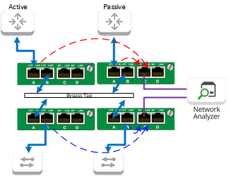
In addition to filtering traffic based on specified criteria, the Filter TAPs inserted into a chassis can make use of the chassis’ 1G backplane. This enables Filter TAPs within the same row to utilize each other’s ports and pass traffic between them. In the situation depicted above, the Filter TAPs are taking the ingress eastbound traffic coming from both the active and passive routers and egressing the aggregated traffic out Port C to the monitoring appliance. The same thing is also happening to the westbound traffic coming from the switch on the other end of the Bypass TAP. Using Filtering TAPs in this way will offer an administrator visibility into network traffic before and after it hits a security appliance, providing the means to evaluate the performance of the appliance. In addition, Port D can be used to add an additional monitoring tool to this environment.
.png?width=500&height=300&name=Bypass%20Tap%20-%20Full%20(1).png) Now, bringing this back home, we can see that the above design is providing resiliency to the network connection by taking the security appliance physically out-of-band, but allowing it to act as an in-line appliance. We can also see that Filter TAPs are being used to target specific traffic flows to feed the Data Loss Prevention appliance both sanitized and pre-sanitized traffic.
Now, bringing this back home, we can see that the above design is providing resiliency to the network connection by taking the security appliance physically out-of-band, but allowing it to act as an in-line appliance. We can also see that Filter TAPs are being used to target specific traffic flows to feed the Data Loss Prevention appliance both sanitized and pre-sanitized traffic.
Have a network problem you want solved? Let our Design-IT Team create a customized network solutionfor you.